XRD

Would You like to receive a quote for XRD equipment?
Send a quick form, email at [email protected] or call at +48 32 614 12 29
Residual stresses can be measured non-destructively with X-ray diffraction method. X-ray diffraction provides reliable and objective data for quality control assessment. X-rays have high energy and short wavelength when compared to visible light making them ideal for probing the interplanar distances in crystalline materials.
X-rays were discovered by German Physicist W. C. Röntgen in 1895. X-rays are electromagnetic radiation having a much shorter wavelength than visible light and therefore are more energetic. Using this additional energy of these “soft” X-rays, we can probe the inter-atomic distance in crystalline materials at a depth of 1-10’s of microns into the surface. Assuming a planar stress state and using the inter-atomic spacing as the ultimate gage length allows us to measure absolute stress without the need for unstressed samples for calibration.
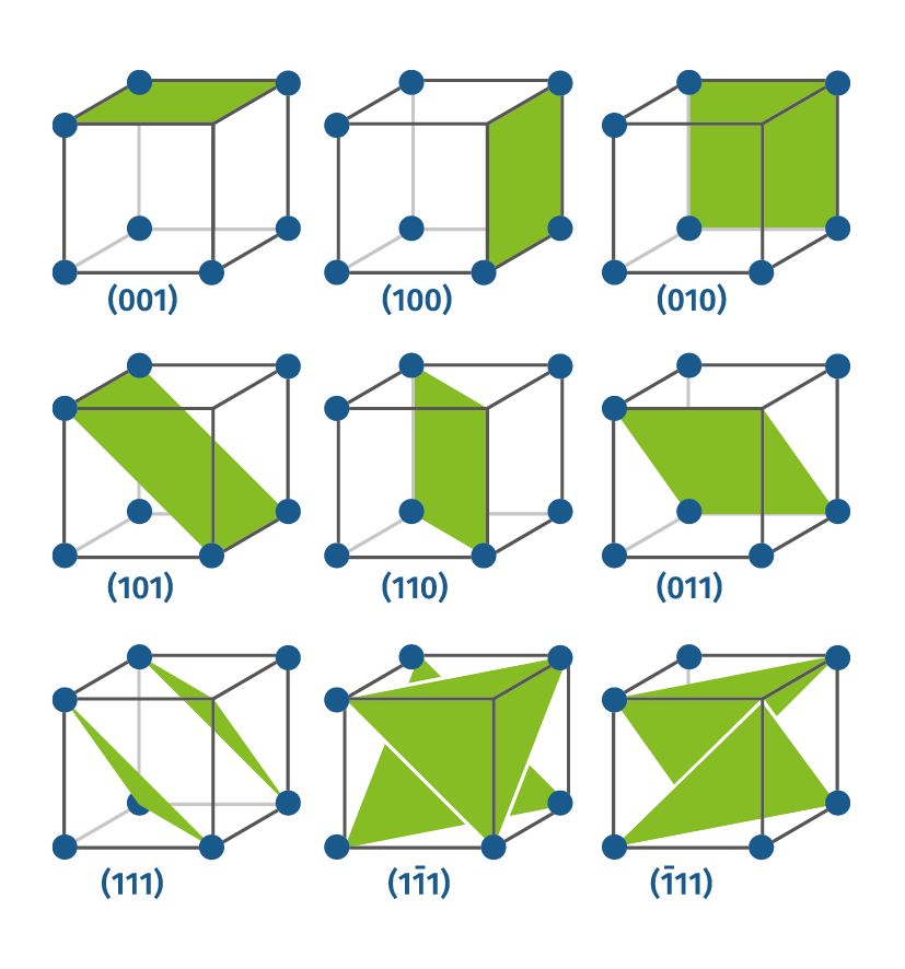
Crystal structure and Miller Indices
Crystalline materials are described by their unit cell, or the smallest volume (a few atoms), that can describe the structure.
An example; Ferritic steel is described as BCC (body centered cubic), a cube with one atom at each corner and one centered in the body. This simple unit cell has the dimensions a=b=c.
Unique descriptive slices can be made through this unit cell and are defined by their Miller Indices. Miller indices are a reciprocal description of a plane that cuts through the unit cell with the terms (hkl). Using ferritic steel as an example again, the (211) plane normally measured is a slice through the unit cell at ½ of a, 1 of b, and 1 of c.
A crystalline material is made up of unit cells of an orientation inside a grain, and then those grains combined together form a nearly homogeneous and random orientation of unit cells inside the small diffracted volume.
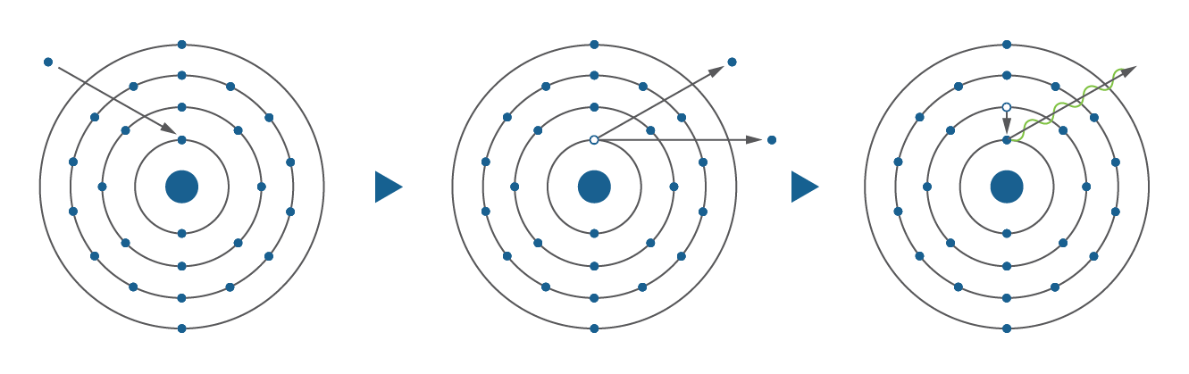
Generation of X-rays
An X-ray tube is the most common source of X-rays. Inside this tube is a tungsten filament that is heated using electrical current, similar to an “old” incandescent light bulb. A high accelerating voltage (typically 30KeV for our equipment) is used between the cathode (filament) and the anode (target) creating an electron beam. When this electron beam collides with the target material, it removes an electron from the atoms lower shell, leaving a hole. Then, when a higher shell electron drops in to fill the hole, characteristic X-rays specific to the anode target material are generated in a near monochromatic wavelength (mainly Kα and Kβ) along with some background, Bremsstrahlung, X-rays. Overall, this process is very inefficient with <1% of the incoming electron energy actually generating X-ray; the rest is wasted as heat out the radiator.
X-ray diffraction from crystal lattice planes (Bragg's law)
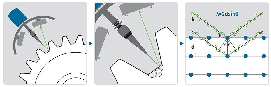
Bragg’s Law was developed by William Henry Bragg and his son William Lawrence Bragg in 1913 and is the basis for describing diffraction. The interaction of the distance between atomic planes, the incoming wavelength, and the angle at which the peak is diffracting is described by:
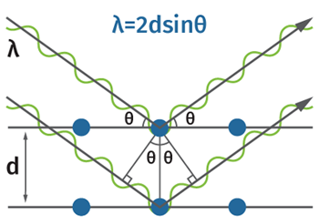
Illustration of the Bragg’s law which describes X-ray diffraction from crystal lattice planes.
or for our use:
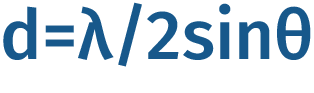
where
λ = Known wavelength of the X-rays.
θ = Diffraction angle
d = d-spacing, distance between atomic planes
This relationship allows us to use the diffracted θ location to calculate the distance between the atomic planes. In practice, for a backscattered diffractometer geometry, the X-ray tube that defines the λ is selected so that θ is maximized for a given sample material specific d. Bragg’s law has proved itself to be accurate and correct, making it useful tool for diffraction applications.
Residual stress determination from the X-ray diffraction data
Using a combination of a material’s known crystal structure and the X-ray tubes characteristic radiation, a suitable diffracted peak with a favorable diffraction intensity and a high 2θ value (2θ>130˚) can be selected for performing measurements.
Assuming a planar stress state in the measured volume, the d-spacing normal to the surface can be used as an unstrained spacing, eliminating the need for an unstrained d value of the sample.
Comparing this 2θ/d-spacing information as the measuring head is tilted away from normal shows us the strain through the change in d-spacing in that direction. This gives linear distribution of d vs sin2c. This slope along with the materials linear elastic parameters (Modulus and Poisson’s ratio) allows for the calculation of the residual stress in the direction parallel to the plane we are tilting in.
By then rotating the goniometer or the sample around the measurement location in 2 additional direction (usually 0˚, 45˚ and 90˚) will give three stress values known directions. These can be used to calculate the planar principal stresses.
Measurements are usually fast; lasting from few minutes to an hour. The irradiated area affects the measurement time; using a larger collimator reduces the needed time to make measurements.

Retained austenite determination
In the case of heat treated low alloy steels, there are 2 phases present;
α-iron: a combination of BCC (body centered cubic) ferrite and/or a BCT (Body centered tetragonal) martensite, the two phases are generally indistinguishable by X-ray diffraction
γ-iron: a FCC (face centered cubic) austenite phase.
By measuring the integrated intensity of the diffracted peaks from each phase and correcting by the diffracting conditions using R-factors, a direct comparison can be made between the corrected integrated intensity ratios and the ratio of Austenite to ferrite/martensite. This comparison can be done on as little as one peak from each phase. A 4-peak comparison (2 ferrite/2 austenite) can also be made giving a standard deviation of the 4 comparisons.
Using “ASTM E 975-13 Standard Practice for X-ray Determination of Retained Austenite in Steel with Near Random Crystallographic Orientation” along with the Xstress 3000, retained austenite issues can be monitored and controlled
Elastic constant determination
The bulk Modulus and Poisson’s ratio values are the average linear elastic parameters for the material from a tensile test. This is the average in all crystallographic directions. In X-ray diffraction, we are only measuring a single diffracted plane in 1 direction relative to the unit cell. So in some cases where the utmost accuracy is needed, it is advantageous to experimentally determine the X-ray elastic constant for a particular diffracted plane.
In the X-ray Elastic Constant (XEC) determination process, the test specimen is bent by applying a load that changes in steps. Xstress 3000 systems make a normal stress measurement during each step. From each measurement, XTronic software calculates the change in interplanar spacing of specific planes. This difference is used for the X-ray elastic constant determination.
Depth profile determination
Residual stresses are rarely completely described by a surface measurement alone. Thermal and mechanical processes generate a residual stress state that varies with depth. To completely characterize these changes, a residual stress depth profile is made. After each measurement, some material (10-500 microns) in a small spot is removed electrochemically to expose a new surface to be measured. The large volume of the part relative to the removed material retains the residual stresses and the electrochemical material removal doesn’t introduce any new stress. The nominal and maximum depth are determined by part specification or from experience with the surface treatment.
Radiation safety
X-rays are ionizing radiation, so safety precautions must be taken into account when performing experiments with X-rays to prevent health hazards to the persons working with the equipment. X-rays are absorbed fairly fast in air, approximately 94% of Cr Kα-radiation is absorbed within 1 meter, but since the primary beam can have a high flux, a safety cabinet for the equipment is highly recommended.
PRODUCERS OF EQUIPMENT AND SYSTEMS FOR XRD
Regarding XRD method Casp System Sp. z o. o. is the distributor of solutions from Stresstech company.
CONTACT
Our NDT specialists are at Your disposal.
In case of any questions regarding our offer please do not hesitate to contact us, our working hours are monday-friday, between 7:30 and 15:30
| Casp System Sp. z o.o. 43-603 Jaworzno, ul. Puszkina 2 NIP: PL 6321873261 | |
| +48 32 614 12 29 | |
| [email protected] |
DISTRIBUTION – ADAPTATION – IMPLEMENTATION – SERVICE
OF NDT EQUIPMENT AND SYSTEMS
A FEW WORDS ABOUT CASP SYSTEM SP. Z O.O.
CASP System company is a well known and respected supplier of equipment and systems from fields such as industrial automation, non destructive testing or research and development.
The company has several departments as well as widely used online stores Manometry24, Czujniki24, Przetworniki24, Enkodery24, Automatyka24, Eh24.pl. During latest years we have expanded our offer considerably and gotten a lot of experience, our personnel is well trained and specialized which is a definite strenght of our company in comparison to our competition. Our additional websites are: WzorceNDT and Aparatura Badawcza

The highest quality of the offered equipment and specialized measurement devices guarantees customer satisfaction and translates into numerous awards that we can proudly display below, for example: